How to make a ultra-soft ball in Blender
(Multilayer Softbody) - HTML Edition
murakoshiA218
November 26, 2015
"How to make a ultra-soft ball in Blender (Multilayer Softbody) - HTML Edition" by murakoshiA218 is licensed under a Creative Commons Attribution-ShareAlike 4.0 International License.
Table of contents
3. Problems and solutions of Softbody
Setting procedure of adding Softbody normally to the ball
Setting procedure of the floor (obstacle)
4. How to build the mesh of Multilayer Softbody
4.1. How to build surface layer
4.2. Assigning Vertex Groups for shaping later
4.3. How to build inner layers
4.4. Adjustment of the distance between the layers
5.2. Simulation and modification
5.2.2 Measures to avoid that Softbody object shrivel
5.2.3 To prevent sinking to the floor
6. Limitations and workarounds
“When you add Subdivision Surface modifier, Mesh will be bumpy.”
“Softbody parameters are not for general purpose.”
(Watch video of this chapter in YouTube: https://youtu.be/-YdTZQvP4gg?t=5s)
NOTE:
I wrote this document by extracting the japanese text from the video below.
”Blenderで超柔らかい球を作る方法 (多層Softbody)”
I translated this document by machine translation and my poor english skills. I think there are many wrong statements and expressions in this document. Please forgive about it.
Blender is an integrated 3DCG software and it is a free software.
Blender has a feature called Softbody to simulate a soft object. However, when normally add Softbody to a 3D object, the object is deformed as rubber membrane is flexed. This is not good-looking.
In this video (this document), I introduces how to build the special Mesh that has internal structure in order to avoid to “deformation as a rubber membrane flexes”. In addition, I introduce an example of the setting of Softbody parameters.
I named this special mesh, "Multilayer Softbody". Because it has multilayer structure by duplicating the surface and shrinking it. In this case, "layer" is independent of layers of the 3D View.
(Watch video from this section on YouTube: https://youtu.be/-YdTZQvP4gg?t=29s)
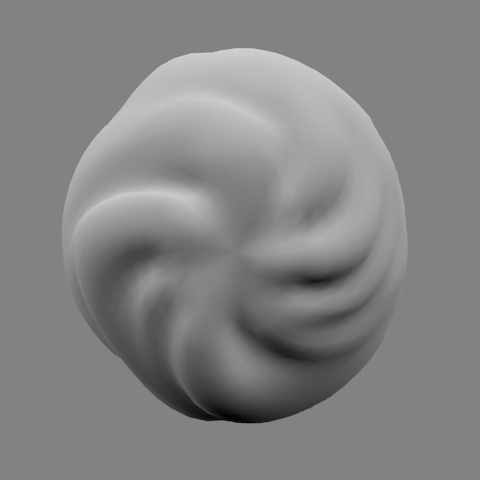
With "Multilayer Softbody", you can create the objects as shown below (See Figure 1, Figure 2).
In this video(this docment), we create a simplified version of "Sample 1".
Compared to the ball to buid in this video, "Sample 1" has half distance between the vertices. The number of vertices is about three times. Therefore, it is little need to change from the procedure, which will be described later. I explain as appropriate, please note.
"Sample 2" has been diverted a sphere made of this video. However, in "Sample 2", because I'm using some techniques that could not be covered in this video, please consider as the application. I explain those techniques on the sequel.
(Watch video from this section on YouTube: https://youtu.be/-YdTZQvP4gg?t=1m20s)
Let's check what happens when normally add the Softbody. Set the Softbody to Ico Sphere, and then we let the free fall it.
Procedure is carried out in the following video is as follows.
(1) Add (Shift + A) → Mesh → Ico Sphere. In Tool Shelf panel, it is set to Subdivisions = 3.
(2) Move "Ico Sphere" upward.
(3) Enable the "Soft Body" in the "Physics" tab.
(4) Decrease the "Cache Step" to 1 in the "Soft Body Cache" panel. (It sets the record accuracy to the highest.)
(5) Set to “Default” = 0 in the "Soft Body Goal" panel. (Force that tries to return to the initial position is set to zero, and it will free fall.)
(1) Add (Shift + A) → Mesh → Plane.
(2) By numerical input, Expand the Plane several times.
(3) Enable the Collision in the Physics tab.
(4) Make sure that it is in the same 3D layer as the object that set Softbody.
When you are finished setting, let's actually simulate.
(1) Please appropriately change the point of view and the display mode.
(2) Change the End Frame from 250 to 100.
(3) Press Alt + A.
Figure 3 What happens when normally apply the Softbody
It was collapsed.
To hard to collapse, Increase "Bending" parameter (the elasticity to bending) from 0 to 0.5.
Figure 4 What happens when you increase the bending parameter to 0.5
It is now collapsed not, but bottom has turned over to the partial..
However, further increasing the value of "Bending" occurs that the entire sphere will be solid.
The reason the ball is dented in part, is because the structure of Mesh inside is empty. In order to prevent this, extrude the edges to the center from each vertex. We will create a center of gravity.
Select all vertices and do Alt + E → "Vertices Only", to extend the Edge from all vertices. Then reduce the size of the vertices to zero. Then press W key and do “Remove Doubles” (remove overlapping vertices).
Figure 5 Softbody ball with center of gravity
(Watch the video from the above-mentioned procedure on YouTube: https://youtu.be/-YdTZQvP4gg?t=3m13s)
The ball with center of gravity is better than it set only "Bending". But soft feel is not good enough.
In order to approach objects in reality, distribute vertices as evenly as possible on the inside of the Mesh. I explored a method that can do with only Blender standard features. As a result, I replicate the vertex, and then shrink to concentrically. However, since the center does not affect too much the surface, it will reduce the number of vertices.
Figure 6 Softbody ball with roughly evenly distributed vertices inside the Mesh
At first glance it is completely useless. It collapsed again.
However, Softbody of Blender has a parameters called "Self Collision". As vertices that make up the Mesh is not hit each other, it is the ability to have a collision detection of spherical for each vertex.
Figure 7 shows the ball enabled Self Collision.
Figure 7 Softbody ball enabled self collision
(Watch the video from the above-mentioned procedure on YouTube: https://youtu.be/-YdTZQvP4gg?t=4m7s)
Finally soft feel came out.
In the following video, I adjusted the parameters of Softbody, and I put a vertical line indicating initial width.
Conveniently, it has a "Spread laterally when compressed vertically" movement.
Figure 8 Softbody ball with Self Collision and adjusted Softbody parameters
It looks in good appearance.
In the next chapter, I'll explain how to build special Mesh that I named "Multilayer Softbody".
(Watch video from this section on YouTube: https://youtu.be/-YdTZQvP4gg?t=4m45s)
To build the concentric Mesh, use the Vertex Group.
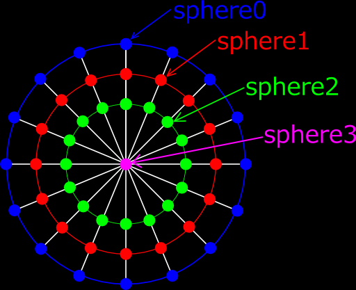
Figure 9 shows concentric Vertex Group that is planning to assign in this chapter. "sphereX" are each Vertex Group.
In Figure 9, there are only four layers, including the center of gravity, but actually we will assign 5-6 layers.
Figure 9 Concentric Vertex Groups that is planning to assign in this chapter
By the way, we use a UV Sphere rather than IcoSphere from now on.
IcoSphere is a good convenient to simulation for vertex evenly is distributed. However, it is difficult to bond to other objects. It is also inconvenient that shaping later. UV Sphere is suitable for them.
(Watch video from this section on YouTube: https://youtu.be/-YdTZQvP4gg?t=5m24s)
Add "UV Sphere" in Object Mode.
In the bottom left of the Tool Shelf panel, set to Segments = 32 and Rings = 16. (When you first create a "Multilayer Softbody", I recommend these values. If you want to reproduce "Sample 1", set Segments = 64 and Rings = 32.)
Enter Edit Mode. Select all vertices. Rotate 90 degrees to the X axis.
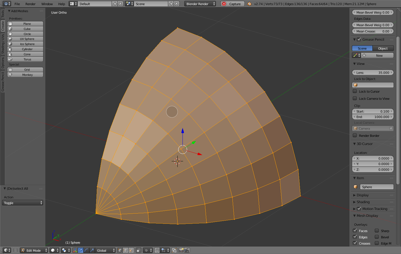
Figure 10 1/8 of the UV Sphere
In Order to reduce the procedure, leaving one-eighth part of "UV Sphere", remove the other vertices. (See Figure 10.)
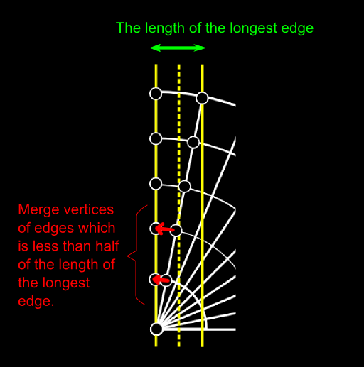
Merge vertices of edges which is less than half of the length of the longest edge. (See Figure 11.)
Figure 11 Merge vertices of edges which is less than half of the length of the longest edge
To merge vertices, select the two vertices, type W key, and select the Merge menu. The second and subsequent operation, you may use Shift + R (repeat last operation).
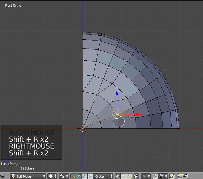
Change the mode of the "Pivot Point" to "3D Cursor". Select all vertices. By repeating the replication and rotation, build a hemisphere. Select all vertices, then do “Remove Doubles”.
Now, the Mesh is not symmetry. Therefore, if you start the simulation, the Mesh will twist. (See Figure 13)
Figure 13 Twisted Mesh because it is not symmetry
So rotate the 5.625 degrees "Merged vertices" to the Y-axis for symmetry. (See Figure 14.)
(5.625 degrees = 360 degrees / 32 Segments / 2)
Figure 14 Rotating merged vertices
(Watch video from this section on YouTube: https://youtu.be/-YdTZQvP4gg?t=7m28s)
In preparation for the case to adjust the shape later as the “Sample 2”, we prepare the vertex groups. These will help you to select vertices. (Use of these Vertex Groups is scheduled to be described in the sequel.)
If you think that "a ball is only to be obtained", please skip this section.
Preparation work is to assign the Vertex Groups to each latitude line of UV Sphere.
Before that, make a ball from the current hemisphere. (Duplicate the hemisphere, and then rotate 180 degrees to the X axis. Select all vertices. Type W key and select "Remove Doubles" menu.)
Figure 15 Assigning vertices to Vertex Groups for shaping
Assign the vertices corresponding to Arctic and Antarctic to the Vertex Group "ring00".
Assign other latitude lines to the "ring01" - "ring15". (See Figure 15.)
We will make sure that Vertex Groups were created. Click the Vertex Group "ring00" in Weight Paint Mode. Hold down the DOWN_ARROW key. (See Figure 16.)
Figure 16 Making sure of Vertex Groups in Weight Paint Mode
(Watch video from this section on YouTube: https://youtu.be/-YdTZQvP4gg?t=9m16s)
I explain most important part of "How to build a Multilayer Softbody" from this section.
Create a new Vertex Group "sphere0". Select all vertices in Edit Mode, and assign them to the Vertex Group.
In order to repeat the following steps, I will write the steps with a number.
The following steps are most important in the building of Multilayer Softbody. It is simple procedure if you get used to it, but It is a little confusing. Please fully understand.
(1)Select the vertices of "sphere0", then duplicate faces of them by pressing Shift+D.
And cancel the moving after duplication by pressing ESC key or right mouse button.
(2)Scale down the duplicated vertices and faces to 0.9 times by typing S key and "0.9".
(3)The selected vertices is assigned to the "sphere0" automatically. Therefore, remove from "sphere0" by pressing “Remove” button in “Vertex Group” panel.
(4)Add new Vertex Group “sphere1”. Then Assign selected vertices to it.
(5)To release all the vertices, press A key. Reselect the vertices of "sphere0".
Extrude the vertices. (Alt + E → "Vertices Only".)
Then cancel moving after extrusion by pressing ESC key or right mouse button.
(6)Scale down the extruded vertices to 0.9 times by typing S key and “0.9”.
(7)The selected vertices is assigned to the "sphere0" automatically. Therefore, remove from "sphere0".
(8)Assign selected vertices to the “sphere1”.
(9)Currently, duplicated vertices and extruded vertices are overlapping.
Therefore, click the Vertex Group "sphere1", and then select all the vertices of the "sphere1"
by pressing Select button. Then, press the W key and do "Remove Doubles" menu.
(You combine the overlapping vertices.)
By the above (1) to (9), we build one of the inner layers. (See Figure 17.)
Figure 17 Building a inner layer
For "sphere2" - "sphere3", please carry out above steps. (If you want to reproduce the "Sample 1", please carried out until "sphere4".)
The last layer is the only center of gravity. Because the vertex has no face, the duplication of faces is omitted. Scale down the extruded vertices to 0 times by typing S key and “0”
(Watch the repetition of steps described above in YouTube: https://youtu.be/-YdTZQvP4gg?t=10m15s)
We'll make sure that the Vertex Groups "sphereX" are assigned to each layer.
Enter the Weight Paint Mode. Press the icon named "Face selection masking for painting". By pressing Tab key, enter Edit Mode from Weight Paint Mode. Select and hide the half of the sphere. Back to Weight Paint Mode by pressing Tab key. You can check the Vertex Group of the remaining hemisphere. (See Figure 18.)
Vertex Groups of "ringXX" were assigned in Section 4.2. You’ll see that they were copied to each inner layers.
Figure 18 Checking inner Vertex Groups in Weight Paint Mode
Vertex Groups had been allocated correctly? If they are wrong, erase wrong Vertex Groups and layers. Then re-build them.
(Watch video from this section on YouTube: https://youtu.be/-YdTZQvP4gg?t=13m25s)
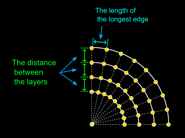
We adjust the distance between the layers to the length of the longest edge that make up the Mesh. (See Figure 19.)
Figure 19 Adjusting the distance between the layers
(1)Select the Ball object and enter Edit Mode.
(2)Select the edge of the equator and the meridian intersect. (That is the longest edge.)
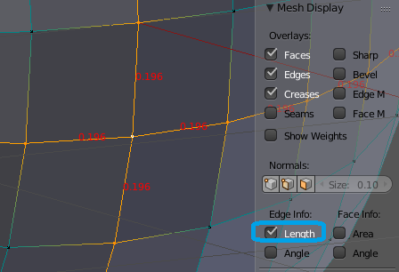
(3)Display the Property Shelf panel by pressing N key, and turn on the Length check box
in the ”Mesh Display” section. Then the length of edges are displayed. (See Figure 20.)
Figure 20 Displaying the length of longest edges
Since we made the UV Sphere which is "Segments = 32", the length of the longest edges will be 0.192. In the following, we will consider this value as 0.2.
Build a ladder-like Mesh for use as ruler. The one step is 0.2. (See Figure 21.)
(1)Add the Plane in Object Mode.
(2)Select all vertices in Edit Mode. Move the corner of the upper left to the origin of the object.
(3)Delete the bottom edge.
(4)Select the remaining edge, and extrude only 0.2 downward. (E key → "-0.2" → Enter)
Repeat the extrusion "the numbers of layers of UV Sphere - 1" times by pressing Shift+R.
(5)Switch to the Object Mode. Move the origin of the ladder-like Mesh to the top of the UV Sphere.
Figure 21 Building a ladder-like Mesh for use as ruler
(Watch the video for the steps above on YouTube: https://youtu.be/-YdTZQvP4gg?t=13m27s)
We must prepare to adjust the distance between the layers. (See Figure 22.)
Select the ladder-like Mesh in Object Mode.
→ Check "Draw All Edges" in the "Object" tab.
→ Hold down the Shift key, and then select additionally the UV Sphere.
(The reason for adding selection is to make it easy to see the ladder-like Mesh.)
→ Switch to the Edit Mode.
→ Turn off “Length” checkbox in Property Shelf panel.
Figure 22 Preparing to scale down the inner layers
We adjust the distance between the layers. (See Figure 23.)
Choose the vertices of the innermost layer. (Click the Vertex Group "sphereX" , and press the Select button.)
→ Scaled down to fit on the stage of the ladder-like Mesh.
→ Scaled down other vertices in the same way for the other layers.
Figure 23 Scaling down the inner layers
Building the Mesh of "Multilayer Softbody" is now complete. Remove the ladder-like Mesh.
(Watch video from this section on YouTube: https://youtu.be/-YdTZQvP4gg?t=14m36s)
First we will create a floor and move the ball upward. Then set the parameters of Softbody. Simulate Softbody. Finally, we will solve the problems found.
First, you set the the End Frame of animation to 100.
(1) Press Shift + C to move the 3D cursor to the origin.
(2) Add a Plane at the origin in Obejct Mode(Shift + A → Mesh → Plane).
(3) Expand several times the Plane.
(4) Enable Collision in Physics tab.
(5) In order to the ball is to prevent penetrate the floor, please set the "Inner" 1.0.
(6) Verify that created "Plane" is in the 3D layer where Softbody object exists.
(1) Select the ball in the Object Mode.
(2) Move to a little distant upward the ball from the floor.
(3) Enable Softbody in Physics tab.
Set as follows in Physics tab.
Mass = 12: Inertia (difficulty in movement). Increase moderately. End = 100: Take the same value as the "End Frame" of animation. Cache Step = 1: Interval to record the results of the simulation (in frame). If the value is 2 or more, the motion is interpolated. | Figure 24 Parameters of Softbody #1 |
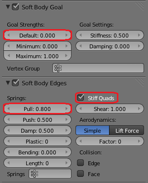
The Default = 0: Make sure to zero in order to free fall. (This is the same as that you disable the "Soft Body Goal". But, to use the Goal In the sequel, we set as described above.) Pull = 0.8: Resilience when edges is pulled. Stiff Quads = Enabled: It will put a spring in the diagonal of the square faces. As a result, it will be less likely to be wrinkles. | Figure 25 Parameters of Softbody #2 |
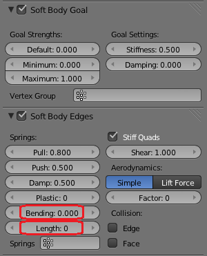
Bending = 0: Bending elasticity. Increase if the Softbody object is too partially deformed. Then Softbody object becomes hard overall. At beginning, set to zero. Length = 0: Reduction ratio (in %). 0 means disabled (equal to 100%). Without changing the other parameters, if you want to reduce the size of the Softbody object, please lowered to 99 below. | Figure 26 Parameters of Softbody #3 |
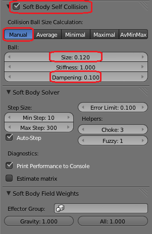
Soft Body Self Collision = enabled: This setting enables the spherical collision detection between vertices. Manual: The size of the collision balls is to be specified in absolute value(rather than the ratio of the length of edges). Size = 0.12: The radius of the collision balls. Set to 60% of the length of the longest edges in the Mesh. We will later fine-tune the value. Dampening = 0.1: Attenuation of the collision balls. Increase the value if the Softbody object tremble finely. | Figure 27 Parameters of Softbody #4 |
Print Performance to Console = enabled: This will display the progress of the simulation to the system console. (Even if reaction of Blender becomes heavy, you can see the progress.) Gravity: Adjustment factor of fall speed. When clicking the left mouse button, you can enter the value greater than 1.0. | Figure 28 Parameters of Softbody #5 |
Setting of Softbody parameters is now complete.
We start the simulation of Softbody.
Figure 29 First simulation of Softbody ball
Did you notice that Softbody object has shriveled as a whole? (See Figure 29.)
The reason is, because the Self Collision does not work only in the part of the vertices (at least in Blender 2.67 and earlier). The "part of the vertices", it is vertices of the first half of the defined order.
If this happens, we duplicate all vertices and faces. Then the number of vertices doubled. (There is a method that rearranges the vertices, I will explain it in the sequel.)
Start the simulation again. (See Figure 30.)
Figure 30 Second simulation after duplicating all vertices
Vertices that was duplicated collapsed because Self Collision does not work. But vertices of the duplication source bulge than a little while ago, tension came out.
Because there is no need to simulate the duplicate vertices, and then secure them to the remote location.
We prevent that the ball sinks to the floor.
To do so, follow the steps given below, and then multiplexes the Mesh. This means that we increase the number of times to detect collision. (See Figure 31.)
(1) Select all vertices in Edit Mode.
(2) Repeat three times to "Shift + D → cancel the moving. (right-click or ESC key)".
Figure 31 Preventing sinking to the floor
The ball is no longer sink into the floor.
Setting of Softbody is now complete.
Each Faces of Multilayer Softbody has the vertical edges. (Mesh is Non Manifold.) When you add Subdivision Surface modifier, Mesh will be bumpy.
To avoid this, follow the steps given below.
(1) Create a Vertex Group that contains only the vertices that make up the surface. (This time, instead of creating a Vertex Group, use “sphere0”.)
(2) Add "Mask modifier". Specify the Vertex Group above to "Vertex Group" field.
Then, only vertices that the Vertex Group includes appears.
(3) Add a Subdivision Surface modifier in last of modifiers stack.
The parameters of the Softbody, there is no set of universal. We need to adjust depending on the situation (speed and vibration period of the movement). Please trial and error.
The following videos are comparison of "Sample 1" and the Mesh that we made in this video.
(1)The Mesh we made (without Mask/SubSurf) Segments=32, Rings=16, Size of Self Collision=1.1, Gravity=1.5. | (2)”Sample 1” (copy of Figure 1) Segments=64, Rings=32, Size=0.085, Gravity=1.0. |
(3)The Mesh we made (with Mask/SubSurf) Parameters are same as (1) | |
Figure 32 Comparison of "Sample 1" and the Mesh that we made
End of File